
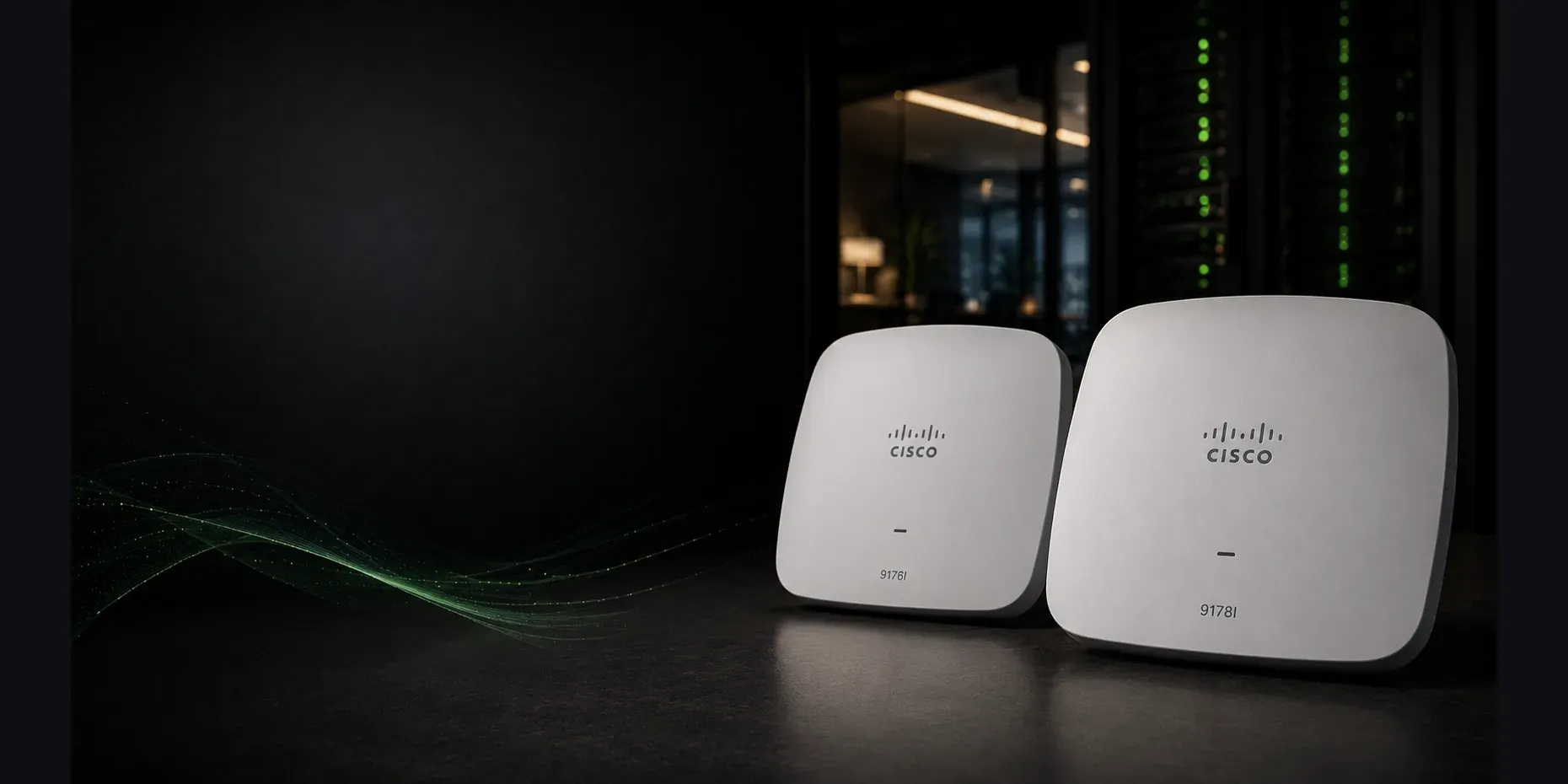
Which Wi-Fi 7 Access Point Fits Your Deployment?
The 9176I offers three flexible client radios and one 10 GbE uplink, while the 9178I adds a fourth radio, up to 16 spatial streams and dual 10 GbE uplinks for density and resilience.
Sekatron Market Intel
Cisco 9176I vs. 9178I at a glance
| Feature | Cisco Wireless 9176I | Cisco Wireless 9178I |
|---|---|---|
| Wireless generation | Wi-Fi 7 | Wi-Fi 7 |
| Client-serving radios | Three | Four |
| Radio configuration | 2.4/5/6 GHz or 5/5/6 GHz | 2.4 GHz, dual 5 GHz and 6 GHz |
| Maximum spatial streams | 12 | 16 |
| Radio capability | 4x4:4 on each active radio at full power | 4x4:4 across four client-serving radios at full power |
| Wired uplinks | One 10 GbE multigigabit port | Two 10 GbE multigigabit ports |
| Uplink resilience | Single Ethernet path | Link aggregation, uplink failover and PoE redundancy supported |
| Full-feature power | 802.3bt Class 5 | 802.3bt Class 6 |
| Typical positioning | High-performance enterprise wireless | Ultra-high-density and resilience-focused wireless |
Cisco describes the 9176I as a tri-band access point with 12 spatial streams. It can operate in either a traditional 2.4 GHz, 5 GHz and 6 GHz configuration or a 5 GHz, 5 GHz and 6 GHz configuration. The 9178I provides four client-serving radios: one 2.4 GHz radio, two 5 GHz radios and one 6 GHz radio, for up to 16 spatial streams.
The biggest difference is the fourth radio
The 9176I can operate with three client-serving radios:
- 2.4 GHz
- 5 GHz
- 6 GHz
It can also repurpose its 2.4 GHz radio and operate with:
- 5 GHz
- A second 5 GHz radio
- 6 GHz
That flexibility allows the access point to prioritize either legacy 2.4 GHz support or additional 5 GHz capacity. Cisco refers to this capability as Flexible Radio Assignment.
The 9178I does not require that trade-off. At full capability, it provides:
- One 2.4 GHz radio
- Two concurrent 5 GHz radios
- One 6 GHz radio
That additional radio can provide more client-serving capacity in environments where all three bands remain important.
The distinction matters most in sites that still require 2.4 GHz for operational or IoT devices while also needing substantial 5 GHz capacity.
When the 9176I may be the better fit
The 9176I is already a very high-capacity enterprise access point.
It may be the more practical choice when:
- Three client-serving radios provide sufficient capacity.
- The site can choose between 2.4 GHz support and dual 5 GHz operation.
- One 10 GbE uplink is acceptable.
- Ethernet and PoE redundancy are not required at each access point.
- The organization wants high-performance Wi-Fi 7 without moving to the largest indoor model.
- Deployment cost and switch-port consumption matter.
At full power, the 9176I supports 4x4 operation on its active 2.4 GHz, 5 GHz and 6 GHz radios and uses a single multigigabit Ethernet interface capable of speeds up to 10 Gbps.
For many offices, campuses and high-density collaboration spaces, that can already provide substantial capacity.
When the 9178I makes more sense
The 9178I is intended for environments that need the additional radio and infrastructure resilience.
It becomes more compelling when:
- Client density is exceptionally high.
- Both 2.4 GHz and two independent 5 GHz radios are required.
- The deployment must support up to 16 spatial streams.
- Dual Ethernet uplinks are valuable.
- Uplink aggregation is part of the design.
- Access-point connectivity must survive the loss of one switch port or power source.
- The switching infrastructure can provide the required power and port capacity.
Cisco documents two 10 GbE multigigabit ports on the 9178I. The ports can support link aggregation, uplink high availability and PoE-source redundancy. In a dual-homed design, they may also connect to separate switches.
That is a meaningful architectural difference — not merely a higher throughput specification.
Dual uplinks do more than increase bandwidth
The second Ethernet port on the 9178I can serve several purposes.
Link aggregation
Both interfaces can be combined to increase available wired capacity for the access point.
Uplink redundancy
If the active Ethernet path fails, the second port can take over with minimal traffic interruption.
PoE redundancy
The access point can negotiate power on both ports. If the primary power source fails, the secondary port can provide continuity.
Dual-homed deployment
Cisco supports connecting the two uplinks to separate switching infrastructure for increased resilience.
These capabilities are most valuable in mission-critical environments. A standard office may not need two switch ports and two PoE sources for every access point.
Full performance requires the correct PoE
The access switch and power budget must be considered before selecting either model.
Cisco Wireless 9176I
With 802.3bt Class 5 power, the 9176I can operate its radios at 4x4, use its 10 GbE uplink and enable its USB interface.
With 802.3at PoE+, Cisco documents reduced operation: the 2.4 GHz radio moves to 2x2, the wired link is limited to 2.5 Gbps and USB is disabled. Standard 802.3af power is intended only for configuration staging with client-serving radios disabled.
Cisco Wireless 9178I
The 9178I requires 802.3bt Class 6 for full 16-stream, quad-radio operation, two 10 GbE links and USB.
Under 802.3at PoE+, it can operate in reduced quad-radio or tri-radio modes, with lower spatial-stream counts and reduced Ethernet speeds. Standard 802.3af again provides only staging-level operation with the radios disabled.
A buyer should not assume that an existing PoE+ switch will expose the full capability of either access point.
Two 10 GbE ports also mean greater switch demand
The 9178I’s resilience can require twice the access-switch connectivity.
A full dual-homed design may need:
- Two multigigabit switch ports per access point
- Adequate PoE from both ports
- Appropriate link-aggregation or failover configuration
- Sufficient access-switch uplink capacity
- Cabling capable of supporting the planned Ethernet rate
Cisco states that Cat6 or Cat6A cabling is required for 10 Gbps operation on the 9176 Series, while Cat5e can support lower multigigabit rates up to 5 Gbps.
The access-point purchase price therefore represents only part of the deployment cost.
Does the 9178I provide better coverage?
Not automatically.
The 9178I provides greater radio capacity and resilience, but wireless coverage depends on:
- Building materials
- Mounting location
- Channel plan
- Transmit power
- Interference
- Client capabilities
- Regulatory limits
- Access-point density
- 6 GHz availability
The additional radio is primarily a capacity advantage.
It should not be used as a reason to reduce access-point count without a proper wireless design or site validation.
Management options are similar
Both access points are part of Cisco’s unified Wi-Fi 7 portfolio.
Cisco supports cloud-managed, on-premises and hybrid deployment options. The access points can be operated through Meraki cloud management or Cisco Catalyst wireless infrastructure without requiring a hardware replacement solely to change management architecture.
Both models require a Cisco Networking Subscription using the appropriate Wireless Essentials or Wireless Advantage entitlement.
Buyers should confirm the intended management mode and subscription before ordering.
What buyers often overlook
The 9178I’s higher specification can appear automatically safer for future growth.
However, buyers should consider whether the environment can actually use:
- Four concurrent client-serving radios
- Two 10 GbE switch ports
- Class 6 PoE
- Dual-homed Ethernet
- Dual power sources
- Sixteen spatial streams
Unused capability increases deployment cost without necessarily improving user experience.
The opposite mistake is choosing the 9176I without recognizing that converting its 2.4 GHz radio into a second 5 GHz radio removes normal 2.4 GHz client service from that radio configuration.
Sites with a large 2.4 GHz IoT population and heavy 5 GHz demand may find the 9178I’s four-radio architecture more valuable.
Final takeaway
Choose the Cisco Wireless 9176I when the environment needs high-performance Wi-Fi 7, flexible radio assignment and a single 10 GbE access-layer connection.
Choose the 9178I when the project requires four client-serving radios, maximum density, dual uplinks and greater network resilience.
Do not select the 9178I only because it has the larger specification. Select it when the access layer and wireless design can use what it adds.
Why it matters
The 9176I and 9178I are not simply different performance tiers of the same deployment.
The 9176I provides flexible high-capacity Wi-Fi 7 with one 10 GbE uplink and three client-serving radios.
The 9178I adds a fourth radio and dual Ethernet architecture for organizations that need additional density, uplink resilience and power redundancy.
The correct choice depends on whether those additional capabilities solve a real design requirement.
Key details
- Choose the 9176I when
- Three client-serving radios are sufficient · Flexible 2.4/5/6 or 5/5/6 operation meets the RF plan · One 10 GbE uplink is acceptable · Full uplink and power redundancy are not required · High performance is needed without the infrastructure demands of the 9178I
- Choose the 9178I when
- Four simultaneous client-serving radios are required · Both 2.4 GHz and dual 5 GHz service are important · Up to 16 spatial streams provide useful capacity · Dual 10 GbE uplinks are part of the design · Link aggregation, uplink failover or PoE redundancy is required · The access layer can provide Class 6 PoE and sufficient multigigabit ports
- PoE for full operation
- 9176I: 802.3bt Class 5 for 4x4 radios, 10 GbE uplink and USB · 9178I: 802.3bt Class 6 for 16-stream quad-radio operation, dual 10 GbE and USB · PoE+ (802.3at) runs both in reduced modes · 802.3af is staging only
What buyers should consider
Before choosing between the 9176I and 9178I, answer these questions:
Does the site need one or two concurrent 5 GHz radios?
Must 2.4 GHz remain available for legacy and IoT devices?
Is one Ethernet uplink sufficient?
Does the design require uplink or PoE redundancy?
Can the switch provide 802.3bt Class 5 or Class 6 power?
Are enough multigigabit switch ports available?
Can the cabling support the planned Ethernet speed?
Will the client population benefit from the additional radio capacity?
Is Meraki cloud or Catalyst controller management planned?
Does the additional resilience justify the total infrastructure cost?
The 9178I is the more capable model. The 9176I may still be the better-designed deployment.
Sources
- Cisco Wireless 9176 Series Access Points Data Sheet(opens in a new tab)Primary source
- Cisco Wireless 9178 Series Access Points Data Sheet(opens in a new tab)Primary source
- Cisco Wireless Ordering Guide(opens in a new tab)Primary source
- Cisco Wireless CW9178I Access Point Deployment Guide(opens in a new tab)Primary source